Ard-Bot H-Bridge Information
Here is the information on the motor h-bridge chip used to control the Ard-Bot. The chip we use is the Texas Instruments SN754410 Dual H-Bridge. Download it’s datasheet here.
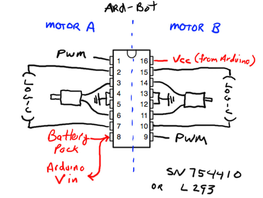
Connections to the Arduino are as follows:
- Pin 1 (Motor A PWM) to Arduino Pin 3
- Pin 2 (Motor A Logic 1) to Arduino Pin 2
- Pin 7 (Motor A Logic 2) to Arduino Pin 4
- Pin 9 (Motor B PWM) to Arduino Pin 5
- Pin 10 (Motor B Logic 1) to Arduino Pin 7
- Pin 15 (Motor B Logic 2) to Arduino Pin 8
- Pin 16 – VCC (5V Power) from the Arduino
- Pin 8 – Motor Power (from the Battery Pack) (also feeds Arduino Vin)
- Pins 4, 5, 12, and 13 are ground (connect 1 to Battery Pack, 1 to Arduino)
- Pins 3 and 6 are Motor A
- Pins 11 and 14 are Motor B
For the Arduino Code we first define the hardware pins
const int motor_A_PWM = 3;

const int motor_A_L1 = 2;

const int motor_A_L2 = 4;
const int motor_B_PWM = 5;
const int motor_B_L1 = 7;
const int motor_B_L2 = 8;
Next we set all these pins to be OUTPUTS
void setup()

{

 pinMode(motor_A_PWM, OUTPUT);

 pinMode(motor_A_L1, OUTPUT);

 pinMode(motor_A_L2, OUTPUT);
pinMode(motor_B_PWM, OUTPUT);
pinMode(motor_B_L1, OUTPUT);
pinMode(motor_B_L2, OUTPUT);
Next for each motor we set one logic control HIGH and the other LOW. Remember the motors will NOT run if both logic controls are set to the same value.
 digitalWrite(motor_A_L1, HIGH);

 digitalWrite(motor_A_L2, LOW);
digitalWrite(motor_B_L1, HIGH);
digitalWrite(motor_B_L2, LOW);
Finally, we turn on both motors at 100 (out of 255) limiting the apparent voltage to the motors to around 3 volts. (If we go higher than this the motors might use too much current and shut down the Arduino board).
 analogWrite(motor_A_PWM, 100);

 analogWrite(motor_B_PWM, 100);
We keep the motors on for 1 second then turn them back off again.
 delay(1000);

 analogWrite(motor_A_PWM, 0);

 analogWrite(motor_B_PWM, 0);

}
void loop()
{
}
Both Ard-bot motors should turn on for 1 second then turn off again. If you have any problems check both your code and wiring carefully. If it works, start playing with different values and perhaps moving some of the commands into the loop function. (but don’t go beyond a value of 100 for the analogWrite commands for now.)
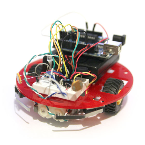
Our most recent class Intro to Arduino Part 2 features the construction and programming of the Ard-bot, a table-top robot which will serve as the standard robot for several more of our classes.
The Ard-bot kit includes
- 5 inch laser-cut acrylic base (see colors below)
- Two-motor gearbox with rubber tires
- Ball-bearing rear caster
- 170 point mini-breadboard
- H-Bridge motor control IC
- AA battery pack with switch (batteries NOT included)
- Two front bumper switches (w/ pull-down resistors)
- Two light-sensitive cadmium sulfide “eyes”
- One RGB LED (w/ resistors) to express “moods”
- A piezo buzzer (to beep and chirp)
- Velcro to attach battery pack and Arduino
- Double-sided foam tape to attach switches
- Shrink tubing to insulate connectors
Retail Price: $49.65
Club Price: $35.00
Acrylic Base Colors
The acrylic bases we use for the Ard-bot are available in various colors. We will make every attempt to get you your color of choice but we’re at the mercy of what is in stock when we place our order.
- Solid Blue
- Solid Green
- Solid Red
- Transparent Grey
- Transparent Red
In addition to this kit you will need…
- An Arduino micro-controller board
- Hook-up wire of various colors
- USB Cable
- A Laptop running the free Arduino software
- A small phillips-head screwdriver
- 4 AA batteries
Note: you will have many of these addition items already if you took the Intro to Arduino Part 1 class.