This is a quick tutorial on programming an ATtiny85 microcontroller using an Arduino Uno board as an In System Programmer (ISP) and the Arduino IDE as the programming environment.
Note: This tutorial assumes familiarity with the Arduino microcontroller, electronic components, and the Arduino software environment.
Most Arduino users will have almost everything they need to program an ATtiny85:
- A Mac, Windows, or Linux computer running the free Arduino software
- A USB cable
- An Arduino Uno board
- A solderless breadboard
- Hookup wires
- An LED
- A matching resistor (somewhere around 330 ohms)
- A 10uf electrolytic capacitor
Probably the only item you will need to add to your kit is the ATtiny85 microcontroller itself. The capacitor also might not be in many starter kits. I’m offering parts kits with 5 ATtiny85s and the capacitor at the bottom of this page. Scroll down for more info.
Once you have everything collected there are 5 simple steps to programming an ATtiny85:
Step 1
Install a set of ATtiny “Cores” into the Arduino software. These compile instruction files allow the Arduino’s software to compile and upload programs to the ATtiny85 microprocessor. There are two popular sources for Core files. The first is MIT who did the initial work in making the ATtiny line of processors compatible with the Arduino programming environment. The second is Google, who have expanded the functions available in an ATtiny core to include nifty things like the tone() function for playing music. If you’re just starting out go with the MIT cores at first then add in the Goggle ones down the road as you need more functionality.
When you download the core files they will come with a set of instructions on how to install them into the Arduino environment. Either set basically amounts to copying some files into the hardware folder inside the Arduino folder on your computer (the folder created by the Arduino software where it stores your Sketches, etc).
Once you have core files correctly installed you will see a number of new entries in the board menu in the Arduino software. So far so good.
Step 2
Next we’ll need an In System Programmer (an ISP) to download data into the ATtiny85 chip. Rather than buy a dedicated one we’ll just use our trusty Arduino Uno and change it into an ISP. First connect the Arduino Uno to your computer using your regular USB cable. Next open the “ArduinoISP” sketch from the Examples menu. Click upload to send this sketch to the Arduino. Congratulations, you now have an ISP.
Step 3
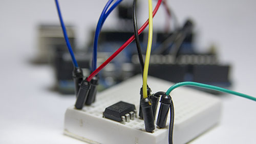
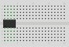
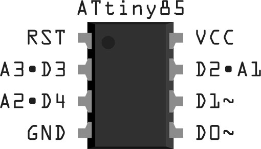
Time to build a simple circuit to connect the ATtiny85 to the Arduino for programming and testing. Let’s start with the ATtiny85 processor itself and the solderless breadboard. On the ATtiny85 chip find the small molded dot that identifies the Reset pin and place the chip into the breadboard as shown here:
Next connect hookup wires between the Arudino Uno and the ATtiny85 on the breadboard as follows:
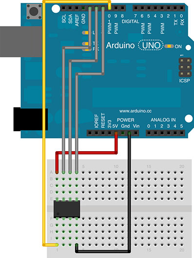
Red wire – 5v power to column 1 top
Black wire – GND to column 4 bottom
Yellow wire – Pin 10 to column 4, bottom
Grey wires – Pins 11, 12, 13 to column 4, 3, 2 top
Next connect the 10uf capacitor between GND and RESET on the Arduino with the negative lead connected to GND.
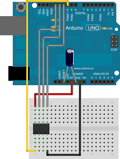
This capacitor prevents the Arduino Uno for resetting itself when the IDE software sends it new data. Instead the ISP Sketch on the Arduino will re-direct the data to the ATtiny85 chip instead.
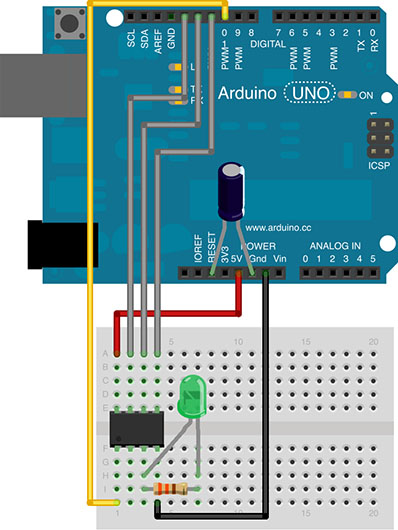
[ERROR: in the drawing above the resistor is connected to the output pin of the ATtiny85. It should go tothe GND pin to the right of the input pin – correction coming]
Finally we’ll add an LED with its anode (long leg) on column 3 bottom of the ATtiny85 chip and it’s cathode (short leg) in a clear column of the breadboard. The 330 ohm resistor will run from this column back to column 4 bottom, the ground pin of the ATtiny85 chip. In the next steps we’ll write a sketch to run on the ATtiny85 to blink this led.
Step 4
Now we’ll set up the Arduino software to communicate to the ATtiny85:
First choose Tools > Programmer > Arduino as ISP to select the Arduino ISP.
Next select Toos > Boards > ATtiny85 (internal 1MHz clock) to select the ATtiny85 chip as our target.
Note that stock ATtiny85 chips run at 1MHz speed so the 8MHz setting won’t work out of the box.
Step 5
Let’s write a quick sketch to turn on the LED attached to the ATtiny85.
Since column 3 bottom is actually the ATtiny85’s digital pin 4 we write:
const int LED = 4;
void setup()
{
pinMode(LED, OUTPUT);
}
void loop()
{
digitalWrite(LED, HIGH);
delay(500);
digitalWrite(LED, LOW);
delay(500);
}
Hit upload and the Arduino software will compile the program and transfer it to the Arduino Uno which will in turn send it on to the ATtiny85. The program should compile to something like 622 bytes (remember the ATtiny85 has 8K of memory total). You may get a warning message to the effect of:
avrdude: please define PAGEL and BS2 signals in the configuration file for part ATtiny85
But this doesn’t seem to cause any problems.
As soon as the upload finishes the LED should light. Congratulations, you’ve just programmed an ATtiny85 chip!
Step 6
Now that the ATtiny85 is programmed (assuming all you want it to do is blink an LED of course) you can remove the Arduino Uno from the picture and power the ATtiny85 directly from two AA batteries:
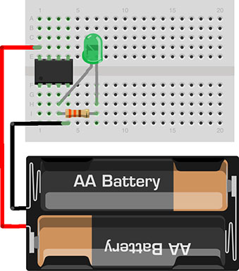
[ERROR: in the drawing above the resistor is connected to the output pin of the ATtiny85. It should go tothe GND pin to the right of the input pin – correction coming]
ATtiny85 5-Pack plus Capacitor
I’m offering parts kits with 5 ATtiny85s and the capacitor with shipping for $15: