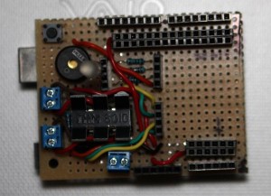
Here is the finished prototype of the RoboShield, a robotics daughter-board for the Arduino microcontroller. Here’s the tour:
- upper-left – reset button
- bottom-left – motor control h-bridge including 2 motor outputs and one motor power input
- left above motor controller – piezo buzzer, RGB LED, and current limiting resistors
- top-right – the Arudino’s 14 digital pins along with ground and 5v busses
- bottom-middle – the Arduino’s power header
- bottom-right – The Arduino’s analog inputs along with ground and 5v busses
- center running vertically – patch bays that allow assignment of the motor control, LED, and buzzer lines to any of the Arduino’s digital pins.
The empty space on the middle-right could be ued for servo motor connects. I’m still trying to decide if I need them.
Because all the component control lines on the board are routed to patch bay headers you have complete control of which Arudino pins you use for what. Also if you’re not using a component it doesn’t need to be taking up any pins
The ground and 5v busses spaced away from the input pins is an idea I borrowed from the MIT HandyBoard that was popular in hobby robtics several years ago (circa 1995). In many ways it was the progenitor of the Arduino
Here’s a page that explains how to connect various sensors to the Handyboard (and now the Robo-Shield as well).